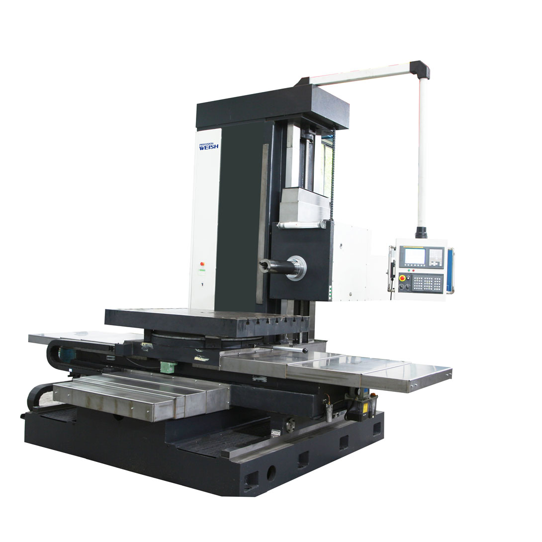
Description
Spindle diameter: ∮130 mm
Worktable horizontal travel (X axis): 2000 mm
Worktable vertical travel (Y axis): 1800 mm
Spindle box vertical travel (Z axis): 2000 mm
Spindle travel (W axis): 900 mm
Panel travel (U axis): 250 mm


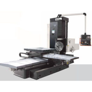
Model: TXK63130
2.1 Name
CNC horizontal boring machine
2.2 Machine operation status
Power supply: 3AC 380V±10% 50HZ±1HZ
Altitude: ≤1500m
Temperature: 5~45°
Relative humidity: ≤85%
Usage environment: The machine should be kept away from vibration sources, heat sources and direct sunlight.

| No. | Specification | unit | TK6113 |
| CNC horizontal boring and milling machine | |||
| 1 | Spindle diameter | mm | φ130 |
| 2 | Spindle top diameter | mm | φ221.44 |
| 3 | Taper | ISO 50( JT50 7:24 ) | |
| 4 | Blindrivet model | D50 DIN69872 | |
| 5 | Power of main motor | Kw | 33/37 |
| 6 | Spindle Speed | r/min | 1-2000r/min |
| 7 | Max. torque of spindle | N.m | 2500 |
| 8 | Max. axial resistance of spindle | N | 20000 |
| 9 | Worktable size | mm | 1800*1800 |
| 10 | Max.loading on table | Kg | 12000 |
| 11 | Worktable transversal travel (X axis) | mm | 2000 |
| 12 | Headstock vertical travel(Z axis) | mm | 2000 |
| 13 | Worktable longitudinal travel(Y axis) | mm | 1800 |
| 14 | Spindle travel (W axis) | mm | 900 |
| 15 | Ram travel (U axis) | mm | 250 |
| 16 | Rotary speed of worktable(B axis) | ° | 360 |
| 17 | The width of T-slot | mm | 28 |
| 18 | Min .distance from spindle top to table center | mm | 100(spindle extend) |
| 19 | Distance from spindle center to the table | mm | 100-2100 |
| 20 | Max. Feeding speed (X axis) | mm/min | stepless,1-6000mm/min |
| 21 | Max. Feeding speed (Y axis) | mm/min | stepless,1-6000mm/min |
| 22 | Max. Feeding speed (Z axis) | mm/min | stepless,1-4000mm/min |
| 23 | Max. Feeding speed (V, W axis) | mm/min | stepless,1-4000mm/min |
| 24 | B axis | r/min | 0~1 |
| 26 | Max. rapid feeding speed (X、Y、V, W axis) | mm/min | 6000 |
| 27 | Max .rapid feeding speed(Z axis) | mm/min | 3000 |
| 28 | Spindle cooling | 20bar | |
| 29 | Protective door plate | CE Nor | |
| 30 | Max.rapid feeding speed (B axis) | º/min | 450 |
3.8 Machine tool electrical
3.8.1 Components:
The electrical equipment of the whole machine consists of a control cabinet, an operation panel, and a handheld operation unit. The whole machine adopts a unified AC three-phase power supply.
3.8.2 Machine working conditions:
Power supply: 380±10%V 50HZ±1HZ
Temperature: 0~45℃ Relative humidity: ≤85%
3.8.3 Electrical configuration—–FANUC 0IMD CNC system
FANUC OIMD basic functions:
Interface Chinese display
Spindle control
Linear interpolation and circular interpolation
Reset
Clearance compensation
Tool geometry compensation
Standard ring with graphic support
Fault diagnosis and display function
Handheld operation unit.
(5) Safety protection measures:
1 Hydraulic over-temperature no-voltage protection;
2 Regularly lubricate the machine coordinates of the oil shortage protection;
3 Spindle drive fault protection;
4 Spindle system overload protection;
5 Spindle automatic tool unloading spindle start interlock protection;
6 Soft limit protection;
7 Overtravel limit protection;
8 Feed drive fault protection;
- Feed system overload protection.
3.10 Complete protection measures:
(1) Hydraulic system temperature and pressure protection;
(2) Machine lubrication system oil shortage protection;
(3) Soft limit protection;
(4) Overtravel limit protection;
(5) Spindle automatic tool unloading spindle start interlock protection;
(6) Spindle system overload protection;
(7) Feed system overload protection;
(8) Spindle direction measurement;
(9) Other mechanical, electrical interlocks, interlock protection.
- Standard layout of machine tool
4.1 Composition of machine tool:
No. Name Quantity
- Horizontal bed of worktable 1 set
- Integral bed machine 1 set
- Rotating slide 1 set
- Worktable 1 set
- Feeding mechanism 1 set
- Two-way bed rail protection 1 set
- Column 1 set
- Vertical guide rail protection 1 set
- Spindle box 1 set
4.2 Electrical part
4.2.1 CNC system, servo drive system
The CNC system uses FANU’s 0IMD system
The feed system uses FANUC’s AC servo drive and this series of servo drives
4.2.2 Control axis
The basic configuration of 5 feed axes and 1 spindle; the definitions of each coordinate axis are as follows:
X axis: horizontal travel of worktable
Y axis: spindle box moves up and down along the column;
V axis: longitudinal travel of worktable;
W axis: ram travel
Z axis: front and rear travel of boring axis;
B axis: NC rotary table rotation indexing
U axis (optional): end feed
All seven feed axes of the machine tool use Japanese FANUC AC digital servo motors (X, Y, Z, V, W, B, U), and each feed motor driver uses a full set of AC feed servo drivers provided by FANUC.
4.2.3 Feedback system
4.2.3.1 Optical ruler configuration (optional function)
X axis: closed loop control
Y axis: closed loop control
W axis: closed loop control
V axis: closed loop control
Z axis: semi-closed loop control
B axis: closed loop control radial grating feedback
- Standard accessories
1 Boring bar 1 set
2 Milling cutter bar; 1 set
3 Reducer sleeve 1 set
4 Short taper shank 1 set
5 Anchor bolt 1 set
6 Iron pad 1 set
- Special accessories (extra charge required)
Handle universal milling head
Various right angle heads
Chip conveyor
Repeat positioning accuracy: X, Y, V, Z, W axis 0.015/500
0.025/1000 mm
B axis ±5〞

Reviews
There are no reviews yet.