Description
Product introduction:
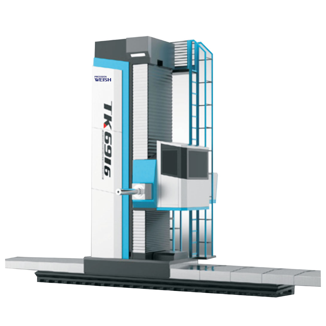
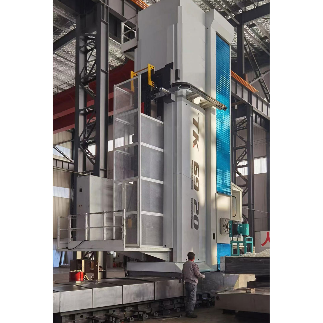
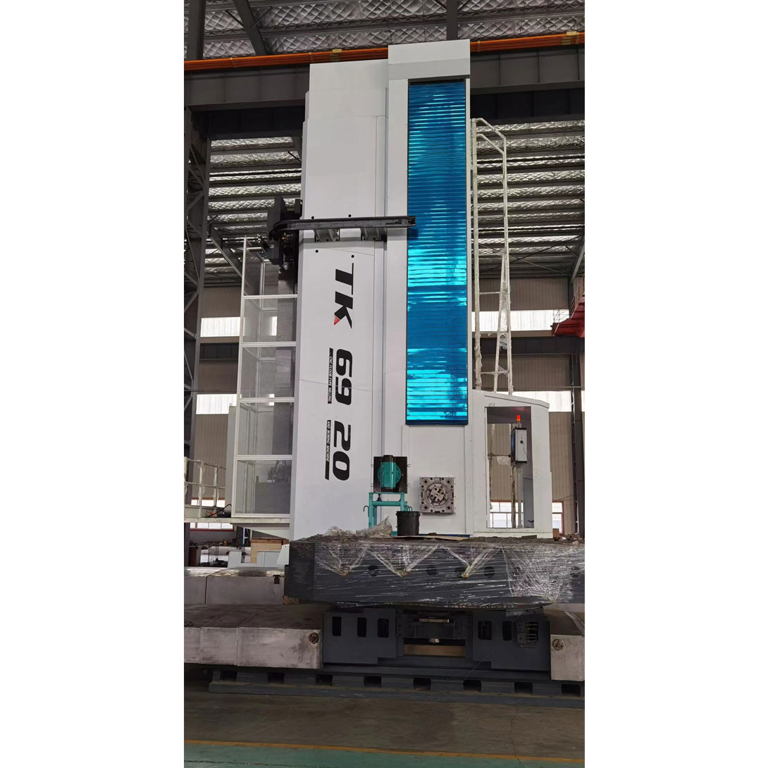
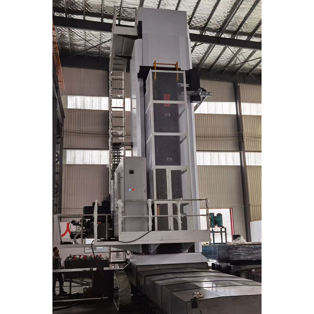
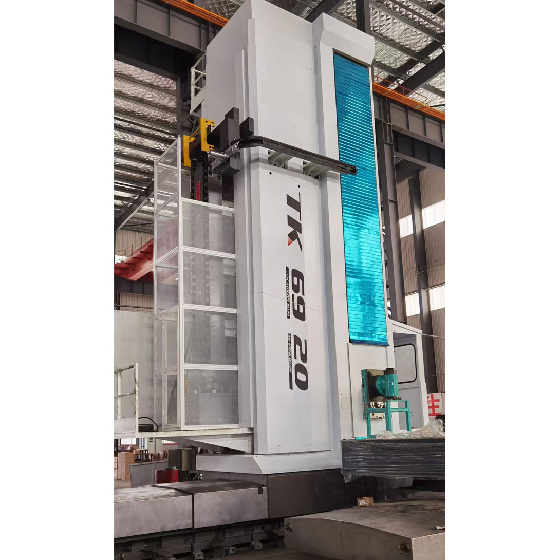
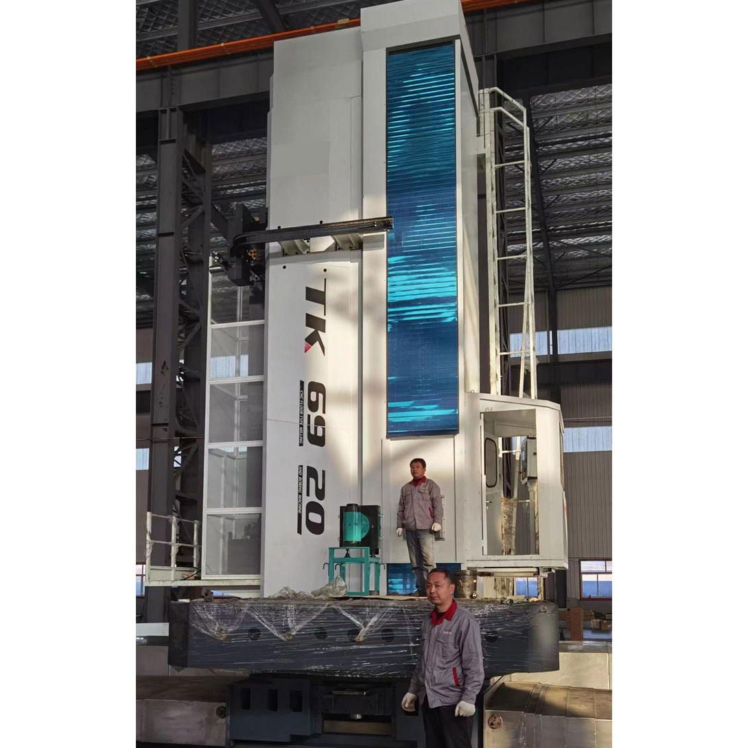
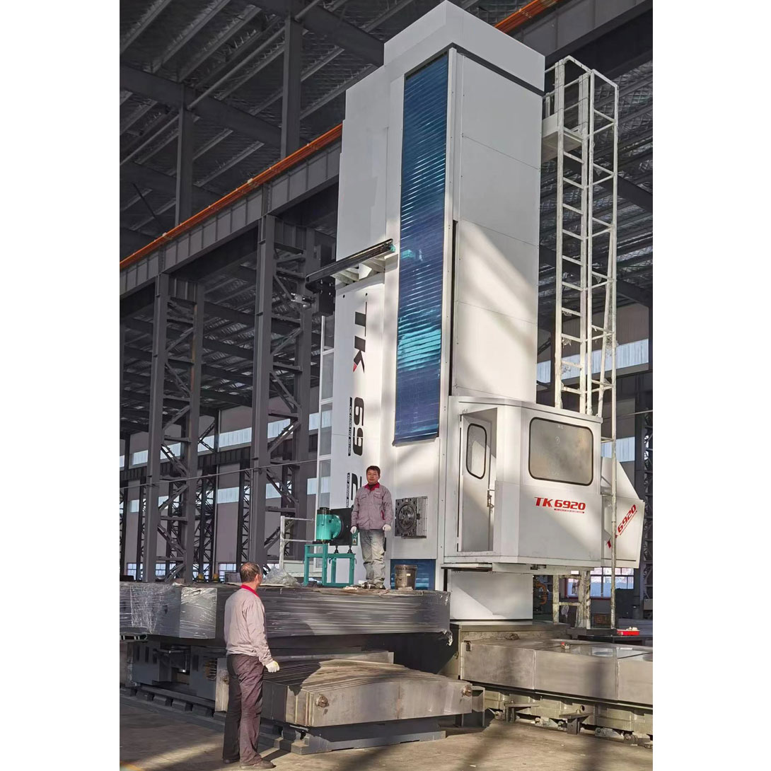
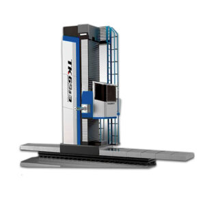
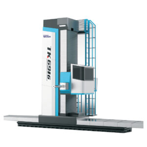
TK6913/16/20 series CNC floor-standing boring and milling machine is designed and manufactured with modern mechanical, electrical, hydraulic and other new technologies. It has excellent performance, wide processing technology, high precision, high reliability and high rigidity. The machine tool can realize multi-axis control and arbitrary four-axis linkage. After the workpiece is clamped once, it can complete drilling, reaming, boring, cutting grooves, plane milling, and boring or milling of three-dimensional curved surfaces and internal threads, which can effectively shorten the auxiliary time and complete one-time clamping and multi-process processing. It is an indispensable processing equipment for industrial sectors such as heavy machinery, engineering machinery, locomotives and vehicles, mining equipment, large motors, turbines, steam turbines, ships, steel, military industry, nuclear power, and large environmental protection equipment. In particular, it can be used in conjunction with a variety of special accessories (vertical milling head, all-purpose milling head, extension milling head, flat rotary disc, etc.), which can further expand the scope of use of the machine tool. The machine tool has a wide range of processing technologies, and the machine tool layout can be arranged according to user requirements.
Product Use
- a) Parts produced repeatedly in small batches
- b) Parts with complex shapes and high processing precision that cannot be processed by general-purpose machine tools or are difficult to ensure processing quality.
- c) During the processing, multiple processes must be performed, such as milling, boring, countersinking or tapping processes that must be completed in one clamping.
- d) Parts that must strictly control tolerances
- e) Workpieces with large cutting allowances
- f) Shell or box-type parts with difficult-to-measure, difficult-to-control feed, and difficult-to-control cavity dimensions.
- g) Parts whose processes and designs may change


| No. | Specification | unit | TK6926 |
| CNC floor type boring machine | |||
| 1 | Spindle diameter | mm | Φ260 |
| 2 | Spindle top diameter | mm | φ221.44 |
| 3 | Taper | ISO 50( JT50 7:24 ) | |
| 4 | Blindrivet model | D50 DIN69872 | |
| 5 | Power of main motor | Kw | 55
|
| 6 | Spindle Speed | r/min | 2-800r/min |
| 7 | Max. torque of spindle | N.m | 3136 |
| 8 | Max. axial resistance of spindle | N | 31360 |
| 9 | Worktable size | mm | optional |
| 10 | Max.loading on table | Kg | 15000 |
| 11 | Worktable transversal travel (X axis) | mm | optional |
| 12 | Headstock vertical travel(Z axis) | mm | 2000 |
| 13 | Worktable longitudinal travel(Y axis) | mm | 1400 |
| 14 | Spindle travel (W axis) | mm | 900 |
| 15 | Facing slide travel U axis) | mm | 250 |
| 16 | Rotary speed of worktable(B axis) | ° | 360 |
| 17 | The width of T-slot and number | mm | 28 / 9 |
| 18 | Min .distance from spindle top to table center | mm | 100(spindle extend) |
| 19 | Distance from spindle center to the table | mm | 100-2100 |
| 20 | Max. Feeding speed (X axis) | mm/min | stepless,1-2500mm/min |
| 21 | Max. Feeding speed (Y axis) | mm/min | stepless,1-2500mm/min |
| 22 | Max. Feeding speed (Z axis) | mm/min | stepless,1-2500mm/min |
| 23 | Max. Feeding speed (V, W axis) | mm/min | stepless,1-2500mm/min |
| 24 | B axis | r/min | 0~1 |
| 25 | Tool changer (ATC) | Not equipted | |
| 26 | Max. rapid feeding speed (X、Y、V, W axis) | mm/min | 2500 |
| 27 | Max .rapid feeding speed(Z axis) | mm/min | 3000 |
| 28 | Spindle cooling | 20bar | |
| 29 | Protective door plate | CE Nor | |
| 30 | Max.rapid feeding speed (B axis) | º/min | 450 |

| No. | Item | Unit | Parameter | |
| 1 | Table Size | mm | 2000*2500 | 2500*3000 |
| 2 | Rotary table height | mm | 395 | 395 |
| 3 | Total table height | mm | 1075 | 1075 |
| 4 | Max. load of worktable | ton | 20 | 20 |
| 5 | Longitudinal travel(V axis) | mm | 1400 | 2000 |
| 6 | Indexing range | Degree | 360 | 360 |
| 7 | V axis feedrate | mm/min | 4~3000 | 4~3000 |
| 8 | B axis feedrate | mm/min | 3~3000 | 3~3000 |
| 9 | Indexing accuracy | Degree | 0.005 | 0.005 |
Control axis
Basic configuration of 5 feed axes and 1 spindle; the coordinate axes are defined as follows:
X axis: lateral travel of the worktable
Y axis: spindle box moves up and down along the column;
V axis: longitudinal travel of the worktable;
W axis: ram travel
Z axis: front and rear travel of the boring axis;
B axis: NC rotary table rotation indexing
U axis (optional): end feed


Reviews
There are no reviews yet.