Description
1.1 Machine Tool Overview
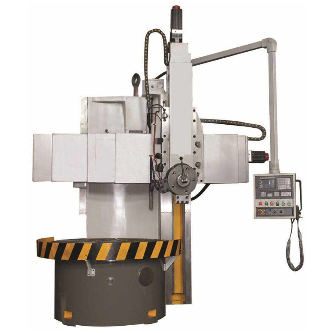
CK5123 is a high-tech mechatronics product that adopts advanced design and manufacturing technology at home and abroad, implements the latest national precision standards, and has high dynamic and static rigidity, safe and reliable movement, long service life, and high processing efficiency. Equipped with advanced functional units. Substantial reductions in structural performance have been achieved.
1.2 Main uses of machine tools
Applicable to high-speed steel, carbide tools, and ceramic tools, it can be used for rough turning and fine turning of outer cylindrical surfaces, inner and outer conical surfaces, threads, arc surfaces, and complex curved surfaces of ferrous metals and non-ferrous metals. And some non-metallic parts.
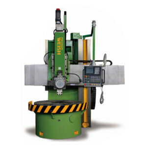
1.3 Main components
The machine tool consists of a workbench, a bed, a gearbox, a crossbeam, a vertical tool rest, a CNC system, an electrical cabinet, etc.
1.4 The warranty period is 1 year.
| Parameter | Unit | CK5123 |
| Max. turning diameter of tool post | mm | 2300 |
| Working table diameter | mm | 2000 |
| Max. height of work-piece | mm | 1600 |
| Max. weight of work-piece | t | 8 |
| Rotation speed range of working table | r/min | 3.2-80 |
| Rotation speed step of working table | step | 16 |
| Feed step of vertical tool post | step | stepless |
| Max. cutting force of vertical tool post | kg | 2800 |
| Max. torque | kg m | 2900 |
| Horizontal travel of vertical tool post | mm | 1200 |
| Vertical travel of vertical tool post | mm | 700 |
| Crossbeam travel | mm | 1100 |
| Crossbeam lifting speed | m/min | 0.44 |
| Main motor power | kw | 30 |
| Dimensions of machine (L*W*H) | mm | 3580*3640*4100 |
| Weight of machine(approx.) | t | 17 |
Main component construction features
3.1 Gearbox
The gear is made of 40Cr material, and after high-frequency quenching treatment, the hardness reaches HRC40-45, and the gear grinder can reach grade 6 precision. This reduces the vibration and noise of the machine tool and improves efficiency and reliability.
3.2 Feeding system
The elastic coupling is directly connected to the ball screw to achieve horizontal and vertical feeding and rapid movement of the tool holder.
3.3 Bed
The overall structure of the bed adopts high-strength, low-stress cast iron parts, and effective vibration reduction measures are taken. The combination of the bed and the workbench base can greatly improve the reliability of the overall rigidity of the machine tool.
3.4 Beam
The contact surface of the beam and the column is pasted with a wear-resistant soft strip of polytetrafluoroethylene guide rail with a small friction coefficient, which greatly extends the service life of the machine. The beam can move along the Z axis on the column guide rail. It is lifted and lowered by the screw, and has the advantages of smooth transmission, low friction, low noise and high reliability. The stainless steel telescopic cover is fixed on the horizontal guide rail of the beam (X axis). The beam fixture adopts a screw clamping mechanism, which is safe and reliable.
3.5 Workbench
The entire workbench structure is a thermally symmetrical structure, and the main speed change mechanism is fixed on the workbench base and the bed. The workbench radial centering adopts high-precision double-row short cylindrical roller bearings to ensure the rotation accuracy and improve the load-bearing capacity of the lathe. The workbench drive gear and all bearings are lubricated by the hydraulic system through a dedicated oil circuit.
The workbench is made of cast iron and has a symmetrical geometric shape to ensure that the workbench moves smoothly within the rated speed.
3.6 Vertical tool holder
The vertical tool holder consists of a beam slide, a rotary slide, a ram and other components.
The vertical tool holder can move horizontally along the beam, and the ram can move vertically. The X-axis and Z-axis are driven by Siemens or domestic well-known brand AC servo motors. The motor and the ball screw are directly connected by a one-way precision diaphragm elastic coupling.
The movement is smooth, the transmission efficiency is high, and the accuracy retention is good. The X-axis and Z-axis guide rails, ball screws, and bearings are lubricated in a fixed time and quantity. The tool holder vertical feed motor (Z-axis) is equipped with a brake to prevent the machine from power failure and tool drop. The slide is made of ball milling cast iron, and the single tool clamp is located at the bottom.
3.7 CNC system
The CNC system uses Siemens GSK. It can realize digital control of the X and Z axes and linkage of the two axes.
3.8 Electrical system
3.8.1 Electrical components are made of Siemens or Schneider to ensure the high reliability of the machine tool.
3.8.2 Electrical components are labeled with clear and durable handwriting.
3.8.3 The wiring of the whole machine is neat, the wire diameter is complete, and the handwriting is clear and durable.
3.8.4 The hydraulic system and automatic lubrication system components are all domestically licensed high-quality products or collaborative products with reliable quality.
Four. Equipment working conditions
4.1 Ambient temperature: 5℃~40℃
4.2 Ambient humidity: 20℃, relative humidity ≤85%
4.3 Machine tool working noise: ≤85 decibels
Machine tool adoption standards and processing accuracy
5.1 Machine tool inspection standards
5.1.1 JB/T 9934.1—1999 CNC vertical lathe accuracy
5.1.2 JB/T 9934.2—2006 CNC vertical lathe technical conditions
5.1.3 GB/T 9061—1988 General technical conditions for metal cutting lathes
5.1.4 GB 5226.1—2002 Industrial machinery and electrical equipment Part 1 General technical conditions
5.1.5 GB/T1742.1—-2000 General rules for machine tool inspection Part 2 CNC axis orientation
5.2 Processing accuracy level IT6~IT7
| No. | Name | Amount | Remark |
| 1 | Lathe bed | 1 | |
| 2 | Work table | 1 | |
| 3 | Vertical tool post | 1 | |
| 4 | Crossbeam | 1 | |
| 5 | CNC system | 1 | |
| 6 | Electric control box | 1 | |
| 7 | Hydraulic system | 1 | |
| 8 | Crossbeam guard | 1 | |
| 9 | Button station | 1 |

Reviews
There are no reviews yet.